See our latest projects and be updated with recent news and features
happening in the world of pneumatic conveying, materials handling
and industrial vacuum systems.
This is the final section of our chocolate milk powder handling plant case study. We present an ordered photo galley of the integrated equipment with a description of each piece and how it works in the plant.
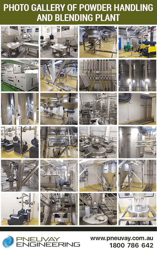
Photo gallery and details of integrated equipment of the chocolate milk powder handling and blending plant
We have compiled an extensive range of photos of the major equipment, how each piece is integrated and used throughout the powder handling and blending plant. The list of photos allows you to tour through the facility following the flow of materials, from receiving through to packaging as the final product.
Unloading stage
Storage stage
Processing stage
Blending stage
Packing stage
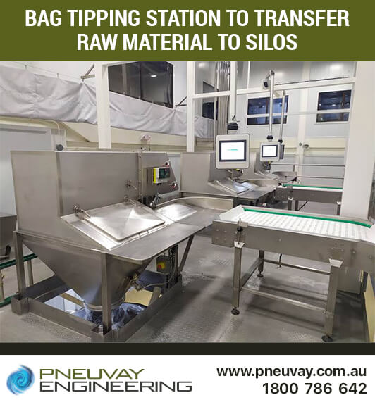
In the foreground, to the left, is bag tipping station 1. This transfers whey powder and processed sugar to silos 1 to 4. In the mid-ground is bag tipping station 2, which transfers the milk powder, creamer and cacao to silos 5 to 8. In the far background, to the right, is bag tipping station 3, which transfers premix to weighing hopper 4.To the right of each station is a mechanical conveyor which transfers 25kg and 50kg bags of material from the ground floor below. In the floor opening beneath each station is the top of the vibratory sifter. The monitors next to the stations are HMIs. Each bag tipping station also has a chain hoist to handle one-tonne big bags. This, however, is not in the photo.
See pictures of the bag tipping station for minor ingredients.
More on how the bag tipping station area functions in the unloading stage.
Bag tipping station for transfer to silos
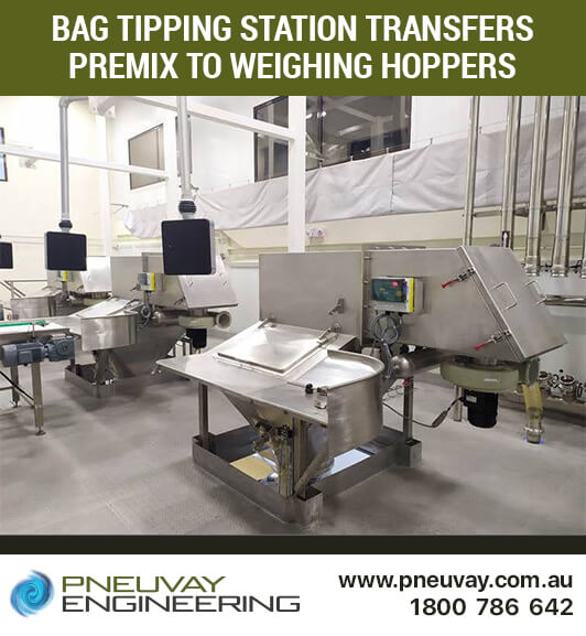
To the right, in the foreground, is bag tipping station 3 which transfers premix to weighing hopper 4. Like the other stations it has a mechanical conveyor, but it is not shown in this photo. The box-like structure and hatch to the top right of each station is an aspiration unit for dust collection.
See pictures of the bag tipping station for raw materials.
More on how the bag tipping station area functions in the unloading stage.
Bag tipping station for transfer to weighing hoppers
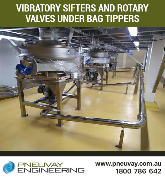
The machines to the left and middle foreground are the vibratory sifters for bag tipping stations 1 and 2. In the background, to the right, is the sifter for station 3. At the top of each sifter is a large, short, clear plastic attachment that connects it to the tipper above. Material is dropped from the stations into these sifters, which sieve them to remove any oversized particles. The sieved material is meted out by the rotary valves at the bottom of each machine, then pneumatically conveyed to the storage silos or weighing hopper 1.The pipework coming in from the right side and passing under the sifters 1 and 2 is three inch 316 stainless steel with short radius bends. Cool dry air is fed in from a nearby dehumidifying unit, booster fan and two pressure blowers. In the background is the same type of pipeline to sifter 3, but it is under vacuum generated from pumps at the weighing hopper structure.
More on how the vibratory sifters and rotary valves area functions in the unloading stage.
Vibratory sifters under bag tipping stations
The cool dry air needed for pressure conveying throughout the processing plant is processed by the dehumidifier unit. This outputs the cool dry air to the green booster fan neighbouring room.
More on how the dehumidifier integrates into the unloading stage.
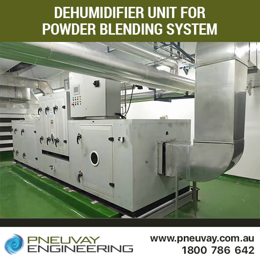
Dehumidifier unit for powder blending system
To the right, in yellow casings, are two powerful pressure blowers. The air from these blowers passes through the nearby dehumidifier unit and booster fan. In a green casing to the background left is a booster fan. The dehumidifying unit, to the right of the booster fan, is connected with a short intake.The booster fan is used to increase output of the cool dry air from the dehumidifier unit. The air transfers material to the silos from tipping stations 1 and 2, also from the buffer hopper to the receiving hoppers. Above the booster fan is a custom-engineered intake manifold connected to the pipework that distributes the processed cool dry air to the blowers, silos and buffer hopper.
More on how the blowers and booster fan integrate into the unloading stage.
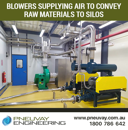
Pressure blowers supply air for conveying of raw materials to silos
Embedded in the pipelines are magnetic separators that pick up material from bag tipping stations 1 and 2. These filter out any metal particles that might have made their way into the processed sugar, creamer, cacao, whey and milk powders.
More on how the magnetic separators integrate into the unloading stage.
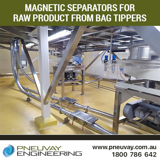
Magnetic separators for raw product from bag tippers
The camlock station manages the flow of raw materials from bag tipping 1 and 2 through the conveying lines to silos 1 to 8. It also manages the premix line from bag tipping 3 to the weighing hopper 1. Material comes from the sifters below and moves up into the processing plant. Raw materials have a conveying rate of five to seven tonnes per hour.In the centre, two flexible hoses feeding into the pipework are for material being pressure conveyed (lean phase) to the silos. The flexible hose and pipeline to the far left are for vacuum conveying (lean phase) to a weighing hopper. The other six flexible hose lines carry cool dry air from the dehumidification unit to the top of the storage silos.
More on how the camlock station integrates into the unloading stage.
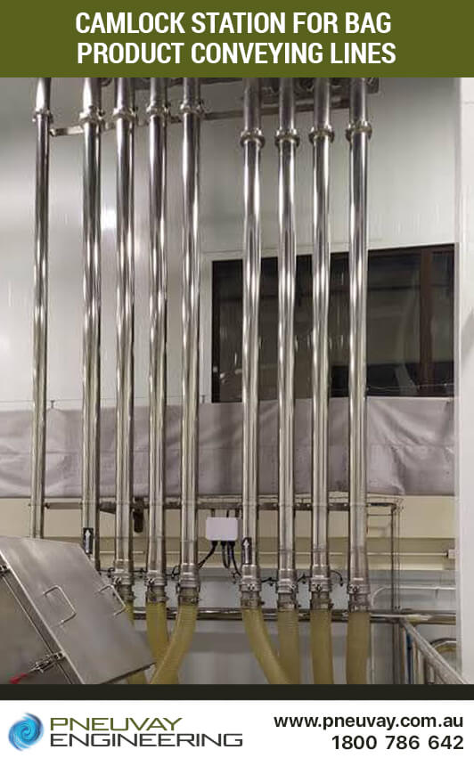
Camlock station for bag tipping conveying line
Aspiration units are the rectangular structures attached to the top of the silos. They are used for dust collecting in the area above and around the silos. The pipework carrying material from the bag tipping stations 1 and 2 are connected to the silos with Toyo spring hoses.
More on how the storage silo aspirators work in the storage stage.
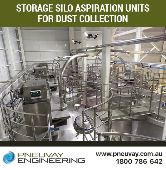
Storage silo aspiration units for dust collection
The storage silos area as seen from the top of the weighing hoppers structure. The rectangular structures at the top of the silos are aspiration units for dust collection. The silos store processed sugar, creamer, cacao, whey and milk powder, each with a capacity of 20 tonnes.
More on how the storage silos work in the storage stage.
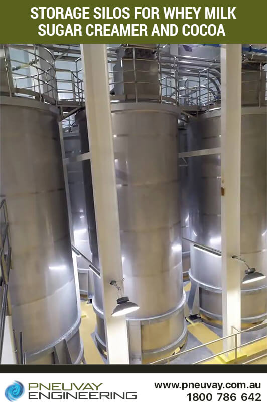
Storage silos for whey milk sugar creamer and cocoa
Three of the eight stainless steel storage silos. At the top are aspirators, while at the bottom are bin activators with rotary values. Material is pressure conveyed from tipping stations 1 and 2 to the top of the silos. Vacuum conveying is used to transport the raw material from the silos to the weighing hoppers.
More on how the storage silos work in the storage stage.
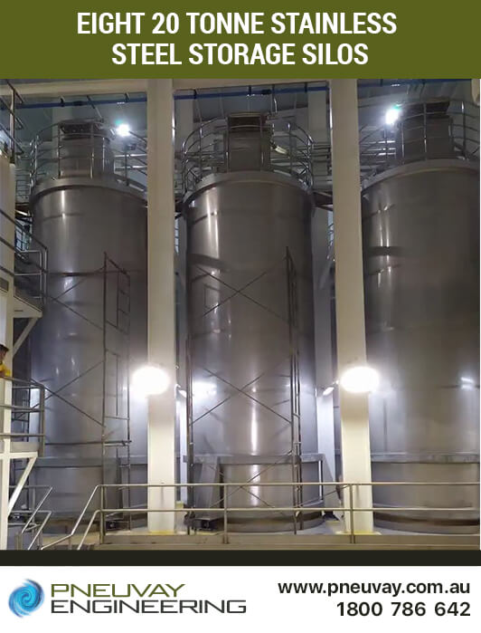
Eight 20 tonne stainless steel storage silos
Each silo has, on the bottom, a stainless steel bin activator and a rotary valve. The rotary valves are connected to the bin activators with BFM flexible connectors and spigots. Material from the silo is dropped into the bin activator and fluidised. It is then meted out by the rotary valves and vacuum conveyed to weighing hoppers 2 to 4.
More on how the bin activators and rotary valves integrate into the storage stage.
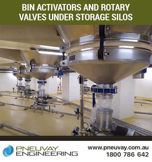
Bin activators and rotary valves under storage silos
The five pipes coming out of the top of the wall are from the silos. They run down along the floor and head off to weighing hoppers 2 to 4 using vacuum to convey raw materials. The pipeline closest in the foreground uses a Y-branch to increase system throughput. The non-abrasive nature of the materials allows for short bends to be used in the pipework.
More on how the dehumidifier and blowers use the pipelines to to provide cool dry air for the plant from the unloading stage.
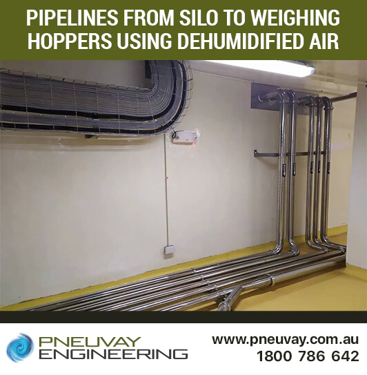
Pipelines from silo to weighing hopper using dehumidified air
This set of vacuum pumps is near the weighing hopper structure area. These are used to lean phase vacuum convey raw materials from bag tipping station 3 to weighing hopper 1, and from the storage silos to weighing hoppers 2 to 4. The raw materials are powders such as whey, milk, creamer and cacao, as well as processed sugar and premix that comes in fine granules.
More on how the vacuum pumps integrate into the processing stage.
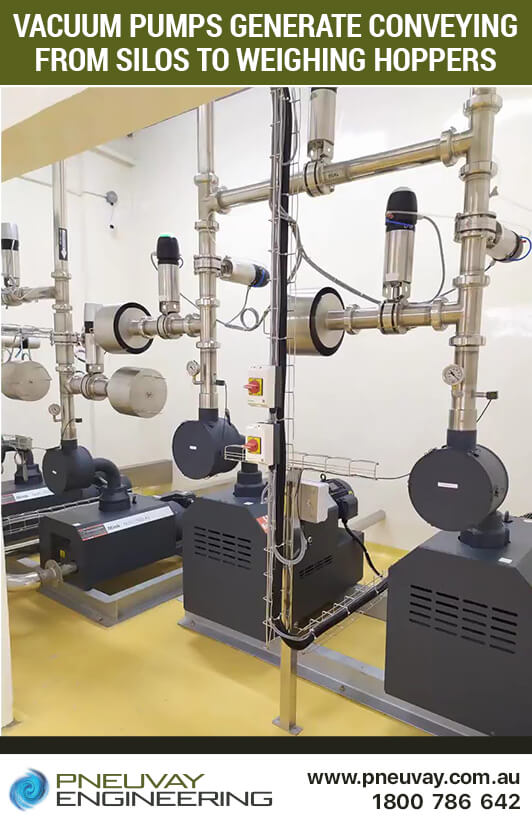
Vacuum pumps generate conveying from silos to weighing hoppers
The weighing hoppers structure has the weighing hoppers at the top on the third level, the discharge chute at the second level, the paddle mixer at the first level and the buffer hopper at the ground level.
More on how the weighing hoppers integrate into the processing stage.
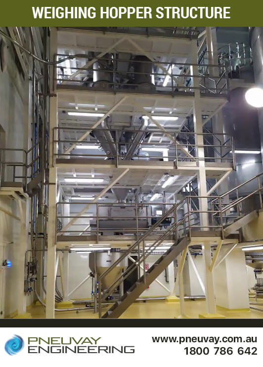
Weighing hopper structure
The circular machines fixed to the top of the weighing hopper structure are aspiration units made of 304 stainless steel connected with Toyo spring hoses. They remove dust from around this weighing hopper structure.
More on the weighing hopper aspirators in the processing stage.
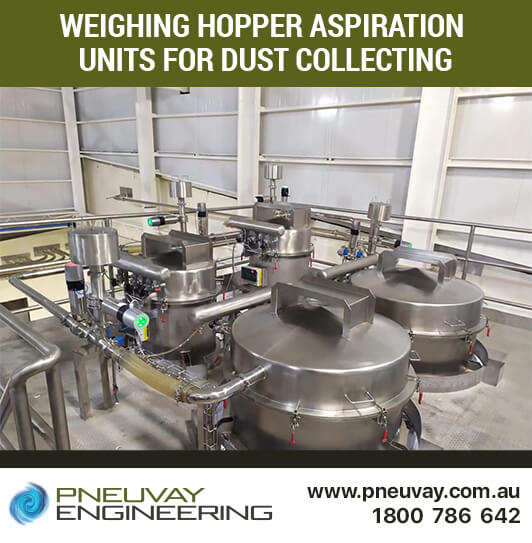
Weighing hopper aspiration units for dust collecting
The four weighing hoppers are filled from the side, not the top. Materials from storage silos 1 to 8 and bag tipping station 3 come in via pipework connected with Toyo spring hoses. Weighing hopper 1 is to the left foreground and is 100 kg in capacity. In the left foreground is weighing hopper 4, which is of 500kg capacity. Weighing hopper 3, 500kg capacity, is in the background to the right. Weighing hopper 2, capacity 150kg, is behind weighing hopper 4 and out of view.
More on the weighing hopper aspirators in the processing stage.
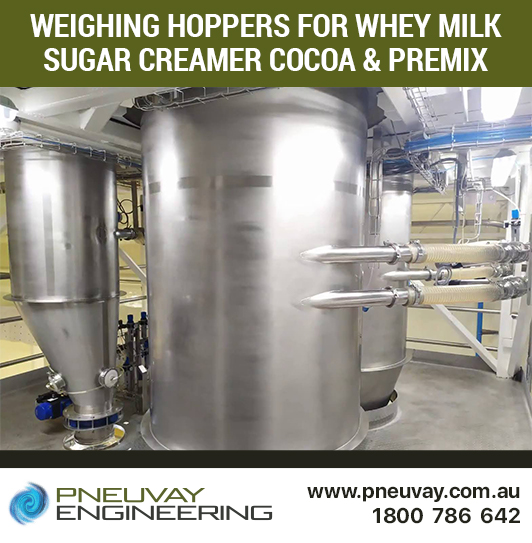
Weighing hoppers for whey milk sugar creamer cocoa and premix
The discharge chute is made of 304 stainless steel, attached to the weighing hopper above and paddle mixer below with BFM flexible connectors. On the leftmost inlet, at the top, a large inspection port is visible. Each of the other inlets has an inspection port, however they cannot be seen from this point of view.
More on how the discharge chute integrates in the blending stage.
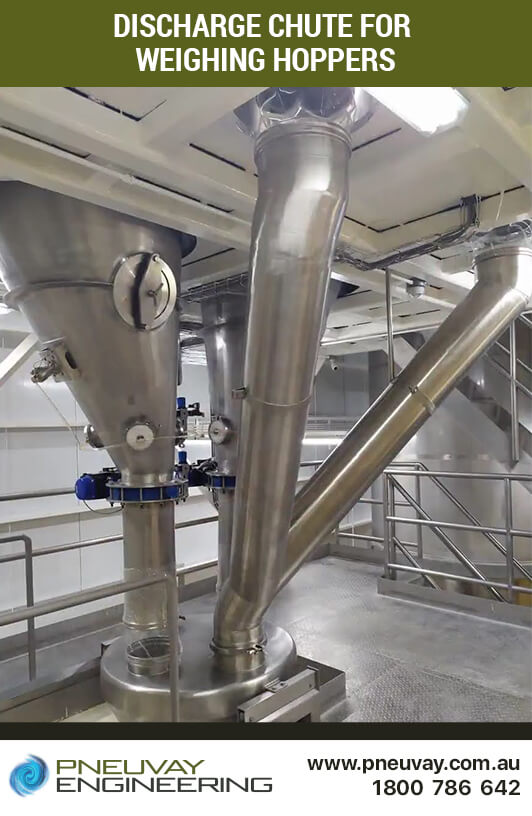
Discharge chute for weighing hoppers
The paddle mixer blends the materials dispensed from the weighing hoppers through the discharge chute and feeds the final product to the buffer hopper below. It is attached to the chute and buffer hopper with BFM flexible connectors and made of stainless steel 316. In the background to the right is a local control panel for the paddle mixer.
More on how the paddle mixer integrates in the processing stage.
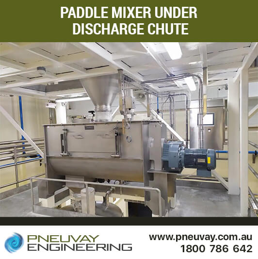
Paddle mixer under discharge chute
The buffer hopper receives the final product from the paddle mixer above. Using dense phase vacuum, it conveys it to the receiving hopper above the packing machines. The hopper is built from 304 stainless steel. The pipework taking the final product to the receiving hopper runs under the hopper to the left side and up the wall. There is a diverter gate in the pipework halfway up the wall. This remotely sends the final product to one of the two receiving hoppers. In the background to the right are the vacuum pumps 1 to 4 used to move materials from silos and tipping station 3 to the weighing hoppers.
More on how the buffer hopper integrates in the processing stage.
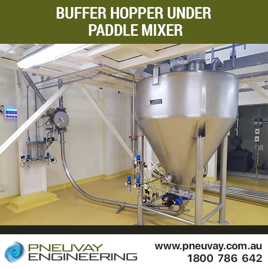
Buffer hopper under paddle mixer
The single pipe that runs through the floor under the buffer hopper and alongside it carries cool dry air from the dehumidifier unit to the top of the buffer hopper. The four pipes running along the floor and up the wall to the rear of the room transfer raw materials from the storage silos to weighing hoppers. The other set of four pipelines running from left to right, midway along the wall to the rear of the room, are vacuum lines.
More on how the pipework and buffer hopper integrates in the processing stage.
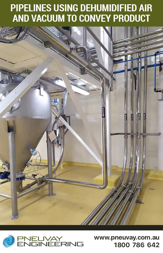
Pipelines using dehumidified air and vacuum to convey product
The receiving hopper structure has two receiving hoppers extending up from the first level to the top. The intermediate and trouser hopper are at ground level. Final product is transferred from the buffer hopper at the bottom of the weighing hopper structure nearby, to the top of the receiving hopper structure. The final product is dispensed to the intermediate and trouser hopper to the packing machines below.
More on how the receiving hopper integrates in the packing stage.
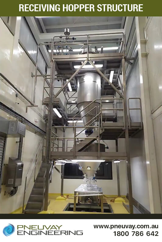
Receiving hopper structure
The intermediate hopper dispenses the final product from the receiving hoppers above and into the trouser hopper below. This hopper is constructed from stainless steel 304 and attached above and below with BFM flexible connectors and spigots. To the left, at the top of the intermediate hopper, is a vent sock, and to the right is a large inspection hatch.
More on how the intermediate hopper integrates in the packing stage.
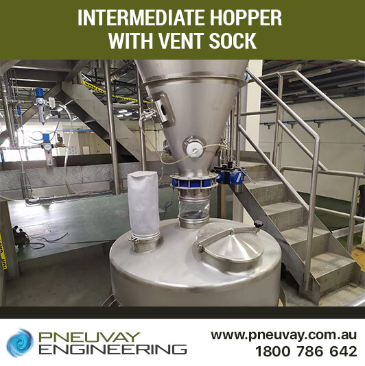
Intermediate hopper
The trouser hopper receives the final product from the intermediate hopper above and feeds it to the packing machines below. It is called a trouser hopper because it looks like the top of a pair of trousers. Custom engineering was required to make this hopper feed material evenly down both sides. It is attached with BFM flexible connectors and spigots, has two vent socks and is made of 304 stainless steel.
More on how the trouser hopper integrates in the packing stage.
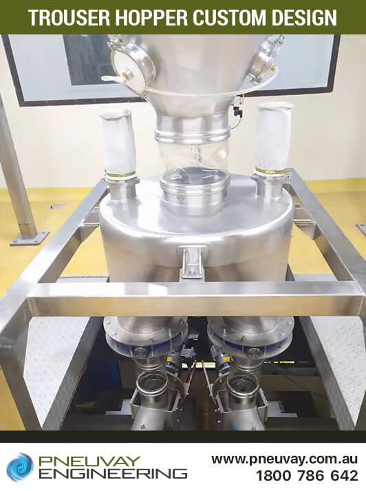
Trouser hopper required custom engineering design
This example of this powder handling and blending plant project is detailed and broken into several major sections including:
Pneuvay is a market leader in powder handling and blending plant system integration. As part of the Pneu Powders Systems group, we cover through the Asia-Pacific to the Middle East. Locally, we cover Australia and New Zealand.
We assist small to large food producers in system integration that involves:
We are experienced in system integration for a wide range of food products such as:
Feel free to contact us if you need assistance in the part or complete design and installation of a powder handling and blending plant. We are happy to help. Call on 1300721458, contact us with our online form or message us on our Facebook page.
Get social with us and see the latest news items from:
Pneuvay Engineering is proud to announce we are the official sole agent for Vortex Australia.
This is a great development for the Australian pneumatic conveying industry.
Read on for more.
Pipe and Tube Compression Couplings
Industrial Dust Collectors Systems
Dust Collectors Filters, Cartridges and Bags


